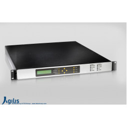
|
Input Parameters
|
|
Input Frequency
|
17.7 to 21.2 GHz
|
|
Impedance
|
50Ω
|
|
VSWR
|
1.5:1
|
|
| |
|
Output Parameters
|
|
Output Frequency
|
950-1700MHz (for Ka to L)
|
|
|
70 ± 18MHz (140MHz optional) (for Ka to IF)
|
|
Impedance
|
50Ω
|
|
VSWR
|
1.5:1
|
|
Input Power
|
+5dBm min
|
|
| |
|
Transfer Parameters
|
|
Frequency spectrum
|
User selectable (for Ka to IF)
|
|
Conversion Gain
|
45dB min
|
|
Gain Adjustment
|
20dB with 0.5dB step
|
| Gain Flatness |
±0.75dB over 36MHz Bandwidth
±1.5dB over Full Bandwidth |
|
Gain Stability
|
±0.25dB over 24hours at constant temperature
|
|
In Band Spurious
|
|
|
Carrier dependent
|
-55dBc at max gain
|
|
Carrier Independent
|
-70dBm max
|
|
Out Band Spurious exclude LO
|
-50dBm max
|
|
Third order intermodulation products
|
-27dBc @ relative to combine power of two carriers at 3dB total power backoff from Rated output power.
|
|
Phase Noise
|
|
|
@1KHz
|
-73dBc/Hz
|
|
@10KHz
|
-83dBc/Hz
|
|
@100KHz
|
-93dBc/Hz (for IF to Ku)
|
|
| |
|
Rear Panel Connections
|
|
IF/L Output
|
BNC Female (for Ka to IF)
|
|
|
N-Type Female (for Ka to L)
|
|
RF Band Input
|
K Connector- Female
|
|
10MHz Ext REF Connector
|
BNC Female
|
|
(Optional)
|
|
|
Remote Connector
|
DB 9 Female
|
|
Power IN
|
AC/DC
|
|
| |
|
Monitor and Control
|
|
Interface
|
RS232/ RS485/ SNMP (Optional)
|
|
Monitoring parameters
|
LO & Temperature Alarms
|
|
Control Parameters
|
Gain Adjustment @ 0.5dB Step
|
|
| |
|
Power Supply
|
|
AC Input Voltage
|
100 to 240VAC 50/60Hz
|
|
Power Consumption
|
35W
|
|
| |
|
Environmental
|
|
Operating temperature
|
0ºC to 50ºC
|
|
Humidity
|
up to 95% (Non-condensing)
|
|
| |
|
Mechanical
|
|
Dimension
|
480L x 330W x 44H mm
|
|
Weight
|
3.5kg (for C to L)
|
|
|
4.0kg (for C to IF)
|
|
| |
|
Compliance Standard
|
|
Inquire
|
|
| |


