Добро пожаловать в IK Tech Corporation
Одна остановка для всех спутниковых потребностей

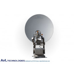
AvL 1810 Premium Military 1,8m Motor Vehicle-Mount Satellite Антенна X-Band

AvL 1810 Premium Military 1,8m Motor Vehicle-Mount Satellite Антенна X-Band

AvL 1810 Premium Military 1.8m моторизованная переносная автомобильная спутниковая антенна 2-портовая X-диапазона

IKtechcorp is дистрибьютор AVL Antanna Systems, ведущего производителя и поставщика коммерческого спутникового оборудования. AVL Technologies предлагает широкий спектр антенн, используемых в VSAT, DTH, COTM, телепортации, кабельном и вещании. Спутник, DTH, VSAT, Flyaway, быстро развертывание, только прием, RF, моторизованная автомобильная точка, автомобильные антенны
• Канал Rx/Tx: 2-портовый военный X-Band
- Прием: - Передача: <

Модель: avl_1810_x_premium_mil

AvL 1810 Premium Military 1.8m Motorized Transportable Vehicle-Mount Satellite Antenna 2-Port X-Band

AvL 1810 Premium SNG/Military 1.8m Motorized Transportable Quad-Band Vehicle-Mount Satellite Tx/Rx Antenna 2-Port Precision X-Band Product Picture, Price, Image, Pricing
 
Summary

AvL 1810 Premium Military 1.8m Motorized Transportable Vehicle-Mount Satellite Antenna 2-Port X-Band

AvL's 1.8m vehicle-mount/drive away Military antenna systems offer strong performance in a small, lightweight and low-profile package. The 1.8m antenna systems offer standard Ku-band, with L- and X-band optional. The antennas feature integrated GPS and level sensors for automatic vehicle tilt compensation.    

AvL’s Military antennas are designed to meet and exceed the highest performance requirements around the world to guarantee both satellite authority compliance and peak in performance, reliability and availability. Typically these antennas are used in signal contribution for high data rate and bandwidth as well as high power broadcast or similar applications.

AvL 1810 X -Band Vehicle-Mount Premium Military Antenna Systems feature:
• Non-load-bearing 1.8m AvL carbon fiber single-piece reflector with surface treatment for Ka-band
• High-precision azimuth bearing
• Integrated backing structure for minimized stow height
• Wide booms to allow larger HPA envelope
• Jog control or fully automatic auto-acquisition controllers
• Feed options for Ku-, Ka- and X-band; optional C-band for international
• RF electronic mounting either on feed boom, back of reflector, base, or inside vehicle
• 25ft (8m) RG59 coax and controller interconnect cables
• Zero backlash AvL Cable Drive with 400° Az & 0-90° El movement
• Stows to 17.7" H (45 cm H)
• Optional saddlebag mount for larger HPAs
• High-torque elevation motor
• Through-pedestal cross-axis waveguide kit
• Optional Transmit Rotary Joint on Feed
• Limited function 3-axis jog controller with auto-stow
• Optional aerodynamic cowlings
• Aerodynamic cowling is available

While the vast majority of military applications to date have relied on commercial satellite interoperability, especially at Ku-band, AvL is now leading the industry in the delivery of systems that will operate over the next generation of military satellites, including Xtar (X-band) and the new US Army Wideband Global Satellite (WGS) constellation (X- and Ka-band). Most of our military antennas can be offered with upgradability to X- and Ka-bands of operation.

AvL antennas interface easily with all RF systems and are compliant with FCC and Intelsat requirements for 2° spacing as well as optional models for meeting Eutelsat and Asiasat criteria. AvL antennas are also in the certification process for operation over the US Army DSCS and WGS satellites.


Technical Specifications Diagram    
Inquire

AvL 1810 Premium Military 1.8m Motorized Transportable Vehicle-Mount Satellite Antenna 2-Port X-Band

MECHANICAL SPECIFICATIONS
   
Az/El Drive Motorized Zero Backlash AvL Cable Drive (Patent Pending)
Polarization Drive System Motorized Worm Drive
Reflector Construction 1.8m Single Piece AvL Carbon Fiber
Axis Travel
Azimuth Standard: 400°;   Optional dual waveguide through pedestal: 270°
Elevation
- Mechanical 0-90° antenna boresight
- Electrical Standard limits at 5° to 65° (CE Approval) or 5° to 90°
Polarization ±95° for 2-port and 3-port Ku-Band Feeds;   ±50° (100º Effective) for Dual Ku-Band, 4-port
   
Az/El Speed
Slewing/Deploying (typical) 2°/second
Peaking (typical) 0.1°/second
   
Motors 24 VDC Variable Speed, Constant Torque
   
RF Interface
BUC Mounting Feed boom (100 lbs.;   Max BUC envelope: 30 L x 22 W x 9 H inches (76 L x 56 W x 23 H cm)) orinside truck
Axis Transition Twist-flex or optional rotary joints for Ku-Band;   Pol rotary joint standard for C-Band
Waveguide WR75 Cover Flange at Interface Point
Coax RG59 run from feed to base plus 25 ft. (8m)
   
Electrical Interface 25 ft. (8 m) Cable with Connectors for Controller
Manual/Emergency Drive Handcrank on Az, El and Pol axes, leads from 12VDC Pol Motor
Weight 295 lbs. (134 kg)
Stowed Dimensions 100 L x 71.4 W x 18.2 H inches (254 L x 181 W x 46.2 H cm); H with opt. controller: 19.3 in (49cm)
Time to Acquisition Less than 15 minutes, 8 minutes typical
Mounting Optional pallet for vehicle roof mounting
 
ENVIRONMENTAL SPECIFICATIONS
   
Wind - Survival Deployed: 80 mph (128 kph); Stowed: 125 mph (201 kph)
Wind - Operational 30 mph (48 kph), Gusts to 45 mph (72 kph)
Pointing Loss in Wind (Ku RX): ▼
20 mph (32 kph) 0.1 dB typical
30 mph gusting to 45 mph 0.5 dB typical


(48 kph gusting to 72 kph)
Temperature:
Operational -22° to 125° F (-30° to 52° C)
Survival -40° to 140° F (-40° to 60° C)
 
RF / ELECTRICAL SPECIFICATIONS Receive Transmit
     
Feed Type X-Band
Frequency Range (GHz) 7.25 - 7.75 7.90 - 8.40
Polarization Configuration RHCP or LHCP LHCP or RHCP
     
Gain (mid-band)

2-Port Feed 41.1 dBi 41.9 dBi
     
Beamwidth    
-3dB (Degrees) 1.6 1.5
-10 dB (Degrees) 2.8 2.6
     
Radiation Pattern Compliance MIL-STD-188-164A
First Sidelobe Level (typical) (dB)

Antenna Noise Temperature (midband) 51° K @ 20° El
G/T, midband, clear horizon 20.9 dB/˚K w/ 55°K LNB
Axial Ratio (CP only, within pointing cone) (dB) 1.21 2
     
Power Handling Capability
1KW per Port
Feed Port Isolation - Tx to Rx (dB) 115 dB (incl. opt. filter) 115 dB (incl. opt. filter)
 
CONTROLLER SPECIFICATIONS
   
Controller Type Three-axis Jog Control & Display with Auto-Stow
Optional Upgrades
Semi-automatic Operation Drive to calculated position based on operator entered vehicle location, heading, plus satellite (longitude or listed)
Automatic Operation Drive to calculated position based on auto GPS and Flux-Gate Compass data & satellite peaking w/ LNB signal
Auto-acquisition One-button acquisition of selected satellite including peaking and optimization of cross-pol (certified for auto- commissioning on most satellite services)
Size Two Rack Units for Semi-automatic & Automatic Controllers
Input Power 110/240 VAC, 1 phase, 50/60 Hz, 10/5 A peak, 1 A continuous
 

CONTROLLER SPECIFICATIONS: OPTIONAL


Optional Controller

AvL AAQ

Features

AvL one button auto-acquisition of selected satellites, including peaking and optimization of cross pol.   Internal movement detector and automatic stow.   Includes a hand-held control and separate power supply.   Certified for auto- commissioning on most satellite services.

Size

Embedded ACU with separate1 RU power supply

Input Power

100 - 240 VAC 50/60 Hz   4 A peak, 300 W power supply

 
Available Options, Upgrades & Services
 
• Upgrade Feed to 3- or 4-Port Ku-Band, 2-Port C-Band, 2- or 4-Port Ka-Band
• Optional H/V switch (Ku Wideband)
• Optional Rotary Joint on Pol Axis with opt. Flex W/G to BUC
• Mounting Pallet (adds 4.5” (11.4 cm) to stow height)
• Add BUC/HPA Mounting (NOTE: minimum elevation may be restricted by these options)
• Upgrade to Custom RF/IF I/O cabling configurations available
• Custom Colorization (contact factory for available colors)
• Add Custom Logo on Reflector Face (1- or 2-Color; per AvL Logo Policy)
• Spare Parts Kit
 
Technical Specifications Diagram
Inquire
 
Compliance Standard
Inquire